When designing high-performance motion systems, engineers often hit a wall with traditional motor architectures. You may need more speed, but the heat becomes unmanageable. You may need smoother rotation, but the “notching” of the motor makes precision control impossible.
This is where slotless stator technology becomes the primary solution. By rethinking the internal geometry of the electric motor, slotless designs eliminate the compromises inherent in traditional “slotted” motors. This guide explores the mechanics, advantages, and trade-offs of slotless stators for intermediate-level engineers and system designers.
Introduction to Slotless Stator Technology
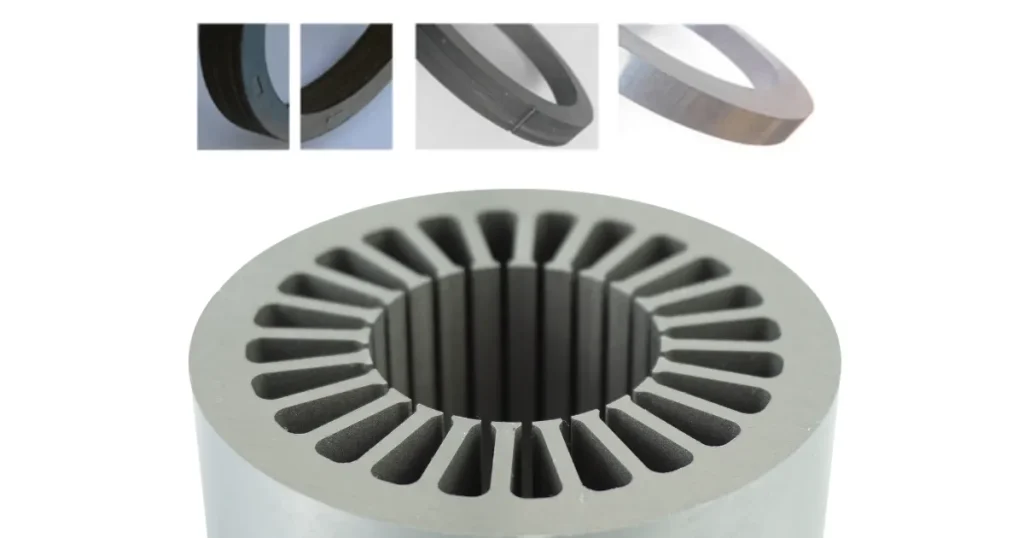
In a standard brushless DC (BLDC) motor, the stator consists of a series of steel “teeth” or slots. Copper wire is wound around these teeth to create electromagnetic poles. While effective for generating high torque at low speeds, the physical presence of those steel teeth introduces several performance bottlenecks.
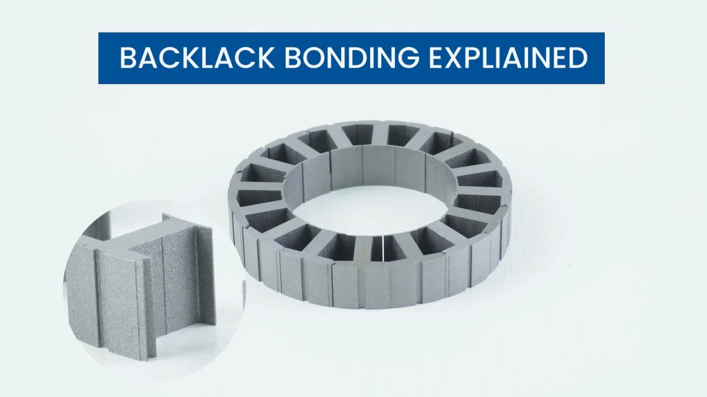
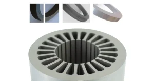
A slotless stator removes the teeth entirely. The copper windings are instead formed into a thin, cylindrical “basket” and placed directly against a smooth, laminated back-iron.
By eliminating the iron teeth, you fundamentally change how the motor interacts with magnetic flux. This architecture is the “clean sheet” approach for applications where vibration, high-speed efficiency, and compact size are the top priorities.
The Physics of Slotless Design: Lorentz Force vs. Reluctance
To understand why slotless motors behave differently, we must look at how they generate motion.
In a slotted motor, torque is generated through a combination of the Lorentz force and reluctance torque. The rotor magnets are physically attracted to the steel teeth of the stator. This creates a “tug-of-war” effect as the rotor moves from one tooth to the next.
In a slotless motor, there are no teeth for the magnets to be attracted to. Therefore, the motor operates almost purely on the Lorentz force. The torque production is governed by the equation:
F=I(L×B)
Because the air gap is uniform and there are no magnetic “speed bumps,” the torque output is perfectly linear relative to the current input. This predictability allows for the extreme precision found in surgical robots and satellite positioning systems.
Key Components & Architecture
A slotless stator might look simpler than a slotted one, but the manufacturing tolerances are significantly tighter. Each component must be optimized to compensate for the lack of a mechanical tooth structure.
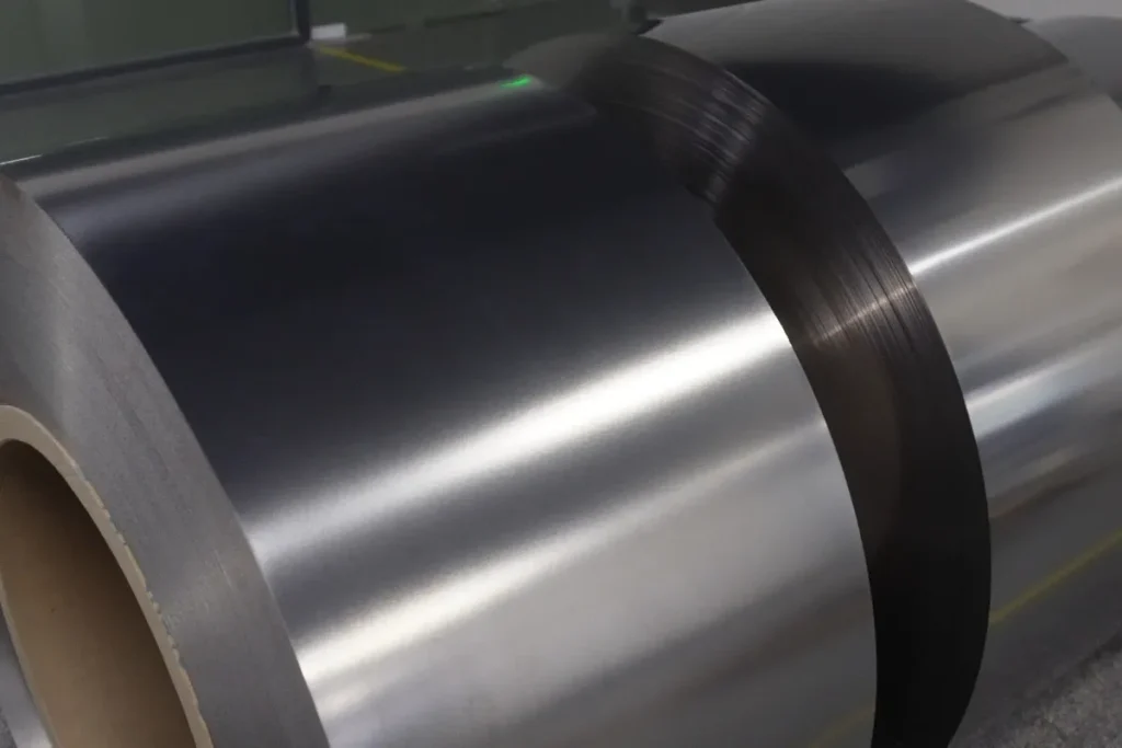
- Laminated Back Iron (Yoke): This serves as the primary return path for magnetic flux. Since the magnetic field doesn’t have to navigate narrow teeth, the yoke can be optimized for weight.
- Copper Winding Array: These are typically “self-supporting.” The copper is wound and bonded into a rigid cylinder before being inserted into the motor.
- Encapsulation and Potting: Since there are no teeth to hold the wires, high-performance slotless motors use advanced epoxy resins to “pot” the windings, providing mechanical rigidity and thermal conduction.
The Problem of Cogging Torque
If you spin a standard DC motor with your fingers, you feel a series of “clicks” or “detents.” This is cogging torque. It occurs because the permanent magnets on the rotor want to align themselves with the stator teeth (the path of least magnetic reluctance).
In a slotless stator, the magnetic resistance is the same at every degree of rotation. There is no preferred position. This results in zero cogging torque.
- Slow Speed Smoothness: You can rotate a slotless motor at 1 RPM without any jerky motion.
- Reduced Noise: Cogging is a major source of audible vibration and “whine.” Slotless motors are significantly quieter.
Comparison: Slotted vs. Slotless Stators
Choosing between these two requires balancing objective trade-offs.
| Performance Metric | Slotted Stator | Slotless Stator |
| Cogging Torque | Present | Zero |
| Inductance | High (Slower current rise) | Low (Rapid response) |
| Heat Dissipation | Direct conduction through teeth | Indirect through potting/air gap |
| High-Speed Efficiency | Limited by iron/eddy losses | Excellent |
| Manufacturing Cost | Lower (Automated) | Higher (Precision assembly) |
Winding Techniques in Slotless Motors
Without teeth to wrap wire around, engineers use specialized patterns to maintain structural integrity.
- Helical Windings: Wires are wound in a continuous spiral. This is efficient for production but can lead to “end-turn” waste where copper doesn’t contribute to torque.
- Diamond (Skewed) Windings: Coils are pre-pressed into a diamond shape and then rolled into a cylinder. This maximizes the amount of copper in the “active” area of the magnetic field.
- Form-Wound Coils: Rectangular or flat wire is used to eliminate air pockets, allowing for a much higher fill factor and power density.
Thermal Management Challenges
In a slotted motor, copper wire is in direct contact with steel teeth, which conduct heat away. In a slotless motor, the copper is effectively “floating” in a sea of resin or an air gap—both poor conductors.
To prevent failure, designers use thermally conductive epoxies loaded with ceramic particles to bridge the heat from the wires to the outer housing. Many high-power designs also require forced air or liquid cooling jackets to maintain their ratings.
High-Speed Performance & Eddy Currents
As speeds increase, the frequency of magnetic flux reversals causes energy loss. Because a slotless stator lacks teeth, the volume of iron exposed to this flux is much smaller. This allows slotless motors to reach speeds of 50,000 to 200,000 RPM with high efficiency.
However, at these speeds, eddy currents can form inside the copper itself. To prevent this, engineers often use Litz wire, which consists of many tiny, individually insulated strands twisted together to prevent the “skin effect” from overheating the motor.
Manufacturing & Assembly Process
The assembly of a slotless motor is akin to watchmaking.
- Precision Tooling: Specialized mandrels hold the winding basket in place. Even a 0.1mm misalignment can cause unbalanced magnetic pull and bearing failure.
- Vacuum Impregnation: To ensure no air bubbles exist in the resin (which cause hotspots), the stator is placed in a vacuum chamber during potting.
- Dynamic Balancing: Because these motors run at extreme speeds, the finished assembly must be balanced to a much higher degree than standard industrial motors.
Critical Application Use-Cases
- Medical Robotics: Surgeons need to feel the resistance of tissue. Cogging torque “masks” this feedback; slotless motors provide the transparency required for haptic systems.
- Aerospace Actuators: In satellites, every gram matters. Slotless motors provide high power-to-weight ratios and zero micro-vibration.
- Optical Scanning: Any jitter in a scanning mirror can ruin image quality. Slotless motors provide the necessary “quiet” rotation.
Selection Criteria for Engineers
When evaluating a slotless motor, look at two key constants:
- Motor Constant(Km): This tells you how much torque you get per watt of heat dissipated. A higher Km indicates a more efficient winding.
- Electrical Time Constant(τe): This is the ratio of inductance to resistance (L/R). Slotless motors have very low inductance, meaning they respond nearly instantly to voltage changes.
Conclusion: Is Slotless Right for You?
The slotless stator is not a universal replacement for the slotted design. If you need massive holding torque at a low cost, a traditional slotted motor is better. However, if your project demands zero vibration, ultra-high RPM efficiency, and a linear torque response, the slotless architecture is the gold standard.
Frequently Asked Questions
Does a slotless motor provide less torque than a slotted motor?
At low speeds, yes. The larger air gap reduces magnetic flux density. However, at high speeds, slotless motors are often more efficient because they lack the iron losses that plague slotted designs.
Why is inductance lower in slotless designs?
Inductance is driven by the presence of iron around the coils. By removing the iron teeth, you increase the magnetic reluctance, which lowers the phase inductance.
Can I use a standard motor controller?
Yes, but ensure it supports a high PWM (switching) frequency. Low inductance can lead to high current ripple, which may stress standard controllers.
Are slotless motors more fragile?
They rely on resin for structural integrity rather than steel teeth. High-quality vacuum potting is essential to ensure the windings don’t shift under centrifugal load.
What is the primary cause of heat in a slotless motor?
At high speeds, AC losses (eddy currents) in the copper windings are the primary heat source, whereas, in slotted motors, heat is often dominated by iron losses in the teeth.